<!-- ### Light Emitting Diode (LED)
An LED is a semiconductor device that emits light when a current passes through it. Most LEDs emit light in a small range of wavelenghts, so that they have a characteristic color. We have LEDs from infrared (~890 nm) through ultraviolet (~400 nm wavelength). A specially deisgned "white" LED emits light over the whole visible spectrum, and appears colorless to our vision.
Most of our LEDS dissipate little power - a few tens of millwatts. More powerful (and cheap) LEDs are available now, in commercial lighting, and also in individual devices.
<img src='./LED.jpg' width="200px" ><img src='./LEDsymbol.jpg' width="400px" >
An LED is shown above. The long leg must be at a more positive voltage than the shorter lead in order for the device to emit light. The electronic symbol is shown on the right. The positive terminal is called the anode, and the negative (lower in this picture) terminal the cathode. In the symbol, the arrow points in the direction that current flows during usual operation of the diode. -->
### RGB (red, green, blue) LEDs
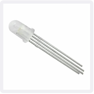
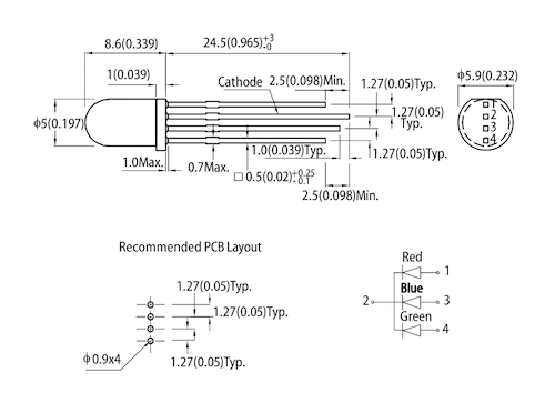
Above is the four-legged RGB LED that we have. Diagrams from the [datasheet](http://www.kingbrightusa.com/images/catalog/SPEC/WP154A4SUREQBFZGC.pdf)
show details of the configuration. The three LEDs within this package have a common cathode (negative terminal). The longest lead is the cathode. Not all RGB LEDs have this arrangement - for each type of RGB that you encounter, you will have to ascertain the arrangement of the leads by testing or referring to the datasheet.
Here is an exaple of code using digital writes to an RGB LED:
```
void setup() {
pinMode(9, OUTPUT); // red
pinMode(10, OUTPUT); // green
pinMode(11, OUTPUT); // blue
}
void loop() {
digitalWrite(9, HIGH); // turn on red channel
delay(500); // delay
digitalWrite(10, HIGH); // turn on green channel
delay(500); // delay
digitalWrite(11, HIGH); // turn on green channel
delay(500); // delay
digitalWrite(9, LOW); // turn off red channel
digitalWrite(10, LOW); // turn off green channel
digitalWrite(11, LOW); // turn off blue channel
delay(3000); // delay
}
```
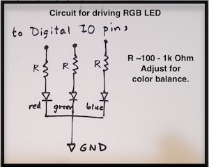
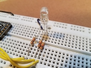
Above is an example of a circuit to drive an RGB LED. The three inputs are connected to three separate digital pins of the microcontroller. If you want to be able to control the intensity of each color, make sure that these pins are capable of PWM (see the pinout diagram for your microcontroller.) The resistors limit the current throgh each LED in the usual way. You may find that the blue LED is less intense - it requires a greater voltage drop than the less energetic green and red. To equalize intensity, you may reduce the resistor value for the blue (and maybe the green) LED relative to the red. Note that the resistors shown here are 1k Ohm (brown, black, red). Refer to the [resistor color code](https://www.arrow.com/en/research-and-events/articles/resistor-color-code) to decipher resistor values for the color-banded resistors.
#### LED arrays
Charlieplexing](https://en.wikipedia.org/wiki/Charlieplexing)
is a way that you can control N*(N-1) LEDs with only N microcontroller ouputs.
#### POV (persistence of vision) LED arrays
[example](https://learn.adafruit.com/bike-wheel-pov-display/overview) and simpler [example](https://maker.pro/arduino/projects/arduino-pov-display)
_Thanks to Rob Hart_