### N20 with Encoder
Sometimes we need a small motor that has both torque and precision (like locomotion for small robots). Small stepper motors (like those found in disk drives) are not very strong. N20 motors are great because they come in a variety of gear ratios, but they are not precise. However, we can find N20 motors with encoders attached, which we can use to measure precision. In this example, we'll write a function to let us use the N20 encoder motor like a stepper motor.
This example uses an ESP32 Dev Board, which means we need to use `ledcWrite()` instead of `analogWrite()`, and need to set PWM properties and configure LED PWM functionalities.
We'll also use the Arduino [Encoder library](https://www.arduino.cc/reference/en/libraries/encoder/). We'll attach the A and B encoder outputs to pins 26 and 25 on the ESP32.
Be careful with the motor pinout. Here's what I see all over the internet, but it doesn't match my motor:
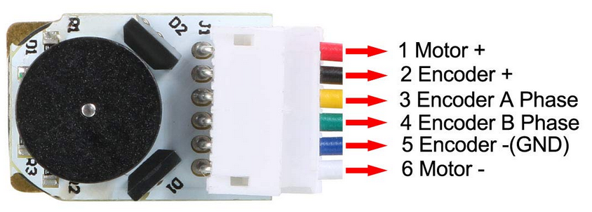
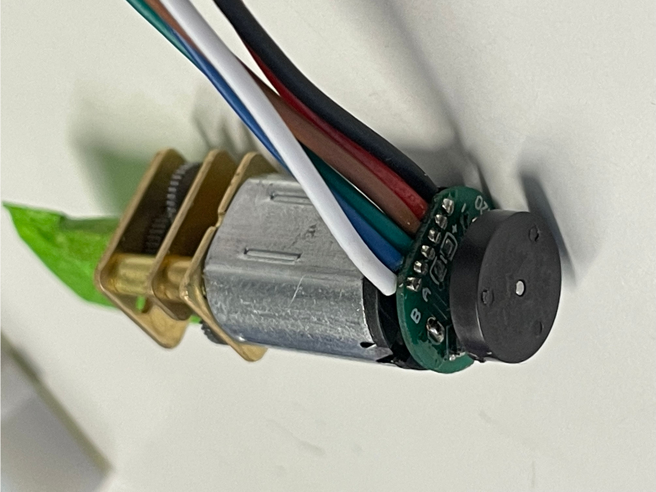
The [motor I have](https://www.amazon.com/gp/product/B07J516Z1L) has a different pinout:
- black: motor power "-"
- red: motor power "+"
- brown: encoder power "+"
- green: encoder power "-"
- blue: encoder output A phase
- white: encoder output B phase
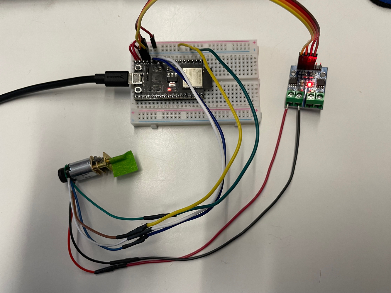
I connected the black and red wires to one port of the L9110 motor driver, which I connected to pins 14 and 27 of the ESP32. I drive the L9110 motor in "Analog mode" as described in the [L9110 tutorial](../../arduino/L9110.html).
I connected the blue and white wires from the encoder to pins 25 and 26 on the ESP32. Encoder pins should be specified as interrupt pins (but the Encoder library already does that for us). Finally, we also connect the encoder to 5 V (brown) and GND (green).
Here's the code I used:
<pre><code class="language-arduino">
#include <Encoder.h>
const int A1A = 14; // define pin 3 for A-1A (PWM Speed)
const int A1B = 27; // define pin 4 for A-1B (direction)
// setting PWM properties
const int freq = 5000;
const int pwmChannel_A = 0;
const int resolution = 8;
Encoder motor_A(26, 25);
long position_A = 0;
void setup() {
Serial.begin(115200);
pinMode(A1A, OUTPUT); // specify these pins as outputs
pinMode(A1B, OUTPUT);
// configure LED PWM functionalities
ledcSetup(pwmChannel_A, freq, resolution);
// attach the channel to the GPIO to be controlled
ledcAttachPin(A1A, pwmChannel_A);
}
void loop() {
moveMotor_A(0, 255); // go to position at full speed
delay(2000); // delay for 2 seconds
moveMotor_A(2800, 255); // go to position at full speed
delay(1000); // delay for 1 second
}
// This is a custom function to drive Motor A
// inputs: target position, speed (0-255)
// outputs: motor control
void moveMotor_A(long target, int spd) {
position_A = motor_A.read();
long steps_to_target = target - position_A;
if (steps_to_target > 0) {
digitalWrite(A1B, HIGH);
spd = 255 - spd; // invert the speed
}
else {
digitalWrite(A1B, LOW);
}
// write spd to the motor until steps reaches threshold
while (abs(steps_to_target) > 10) {
position_A = motor_A.read();
steps_to_target = target - position_A;
// Serial.print("steps_to_target: ");
// Serial.print(steps_to_target);
// Serial.print(", position_A: ");
// Serial.println(position_A);
ledcWrite(pwmChannel_A, spd);
delay(1);
}
// turn the motor off
ledcWrite(pwmChannel_A, 0);
digitalWrite(A1B, LOW);
}
</code></pre>
2800 seems to be the number of "steps" to complete a full revolution for an N20 motor with this particular gear ratio (the Amazon page claims it's 70 RPM).
I picked 10 as a threshold for reaching a target. I haven't tested the performance limits, like how small of a delay can be used.
Here's a demo of the above code, rotating ~360 degrees back and forth.
<video width="320" height="240" controls>
<source src="demo1.mp4" type="video/mp4">
</video>