### Sensing with Step Response (transmit-receive, or tx-rx)
A minimal arduino sketch for taking a single measurement:
```
int analog_pin = A3;
int tx_pin = 4;
int read_high;
int read_low;
int diff;
void setup() {
pinMode(tx_pin, OUTPUT); // Pin 4 provides the voltage step
Serial.begin(9600);
}
void loop() {
digitalWrite(tx_pin,HIGH); // Step the voltage high on conductor 1.
read_high = analogRead(analog_pin); // Measure response of conductor 2.
delayMicroseconds(100); // Delay to reach steady state.
digitalWrite(tx_pin,LOW); // Step the voltage to zero on conductor 1.
read_low = analogRead(analog_pin); // Measure response of conductor 2.
diff = read_high - read_low; // desired answer is the difference between high and low.
Serial.println(diff);
}
```
Arduino sketch with function for tx_rx. Takes the average on N points for a smoother signal. Has the algorithm in a separate function, to make coding easier.
```
long result; //variable for the result of the tx_rx measurement.
int analog_pin = A3;
int tx_pin = 4;
void setup() {
pinMode(tx_pin, OUTPUT); //Pin 4 provides the voltage step
Serial.begin(9600);
}
void loop() {
result = tx_rx();
Serial.println(result);
}
long tx_rx(){ // Function to execute rx_tx algorithm and return a value
// that depends on coupling of two electrodes.
// Value returned is a long integer.
int read_high;
int read_low;
int diff;
long int sum;
int N_samples = 100; // Number of samples to take. Larger number slows it down, but reduces scatter.
sum = 0;
for (int i = 0; i < N_samples; i++){
digitalWrite(tx_pin,HIGH); // Step the voltage high on conductor 1.
read_high = analogRead(analog_pin); // Measure response of conductor 2.
delayMicroseconds(100); // Delay to reach steady state.
digitalWrite(tx_pin,LOW); // Step the voltage to zero on conductor 1.
read_low = analogRead(analog_pin); // Measure response of conductor 2.
diff = read_high - read_low; // desired answer is the difference between high and low.
sum += diff; // Sums up N_samples of these measurements.
}
return sum;
} // End of tx_rx function.
```
Here's how it works:
- transmit (tx) pin is made alternately high (5V or 3.3V) and low (0V). Note that the figures show the number for 5V boards. For 3V boards (like the ATSAM-based Adafruit boards) the highest voltgae is 3.3V.
- This charges and discharges the tx electrode.
- On the rx electrode there is a small 'blip' up or down as the tx pin toggles.
- These blips are measured by the Arduino analog input (ADC), and "low" subracted from "high" (see figure).
- This result varies depending on how closely the two plates are coupled by the electric field. It increases as the distance decreases and also
changes with the amount of overlap and the material between the plates.
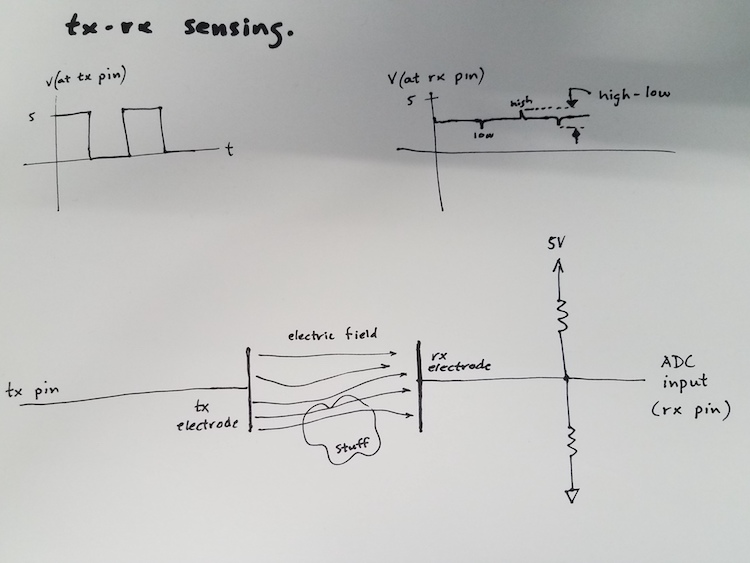
Above is a sketch of the setup for tx-rx sensing. The (optional) resistors between 5V(3.3V) and GND make the signal stabler. The input
to the ADC is attached to the point halfway betwen 5V(3.3V) and ground, and is therefore at 2.5(1.2) volts, except for the transient blips that occur at the tx electrode changes voltage. These resistors should be equal, and should have values of 1 mega-ohm or larger.
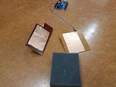
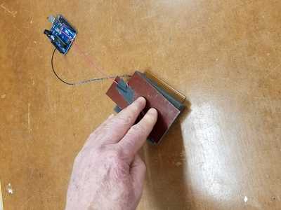
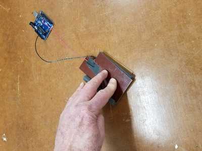
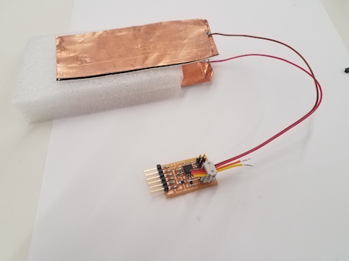
Below are pictures of two copper electrodes (tape on circuitboard material) attached with
no extra resistors to pin4 and A0 of the Arduino. Left, the plates. Middle, the plates with foam between.
Right, the plates get closer together (and the signal increases) when force is applied. Force Sensor!
---
###Several ways to use tx-rx as sensors.
- Proximity between two electrodes lets you measure force through changes in position.
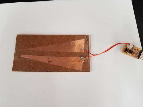
- Wedge geometry as a multi-use sensor.
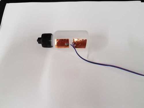
- Tilt sensor. Bottle partially filed with water.
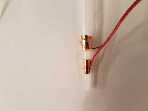
- Pipetter liquid sensor.
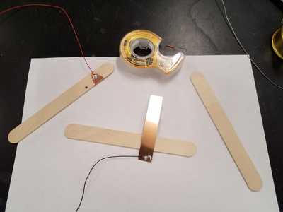
- A crude rotary sensor.
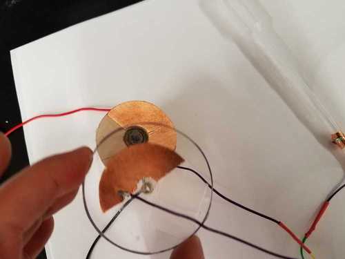
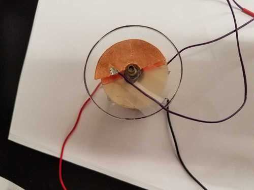
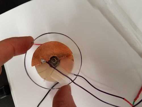
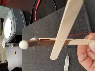
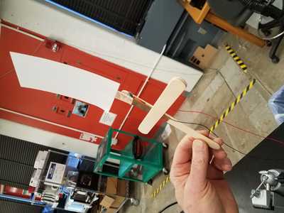
- A popsicle stick arrangment used as accelerometer and wind sensor.
---
_Thanks to Rob Hart_