<h3> Driving a motor with the L9110 </h3>
<p> For this workshop, please collect the following:
<ul>
<li>Microcontroller (MCU): ESP32 dev board or XIAO </li>
<li>DC motor </li>
<li>L9110 </li>
<li>Wires</li>
<li>Small screwdriver</li>
</ul>
</p>
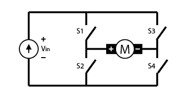
<p> We'll be using the L9110 motor driver to make it easier to control our motors in two directions. See the <a href='https://datasheetspdf.com/pdf-file/839657/ASIC/L9110/1'>L9110 Data Sheet </a>for more information on this component. Under the hood, this component uses the H-bridge confirguration to allow for reversing the direction of the motor. </p>
<p> Note that the L298N motor driver is a more reliable (but slightly more expensive) H-bridge motor driver. See the intructions <a href='https://randomnerdtutorials.com/esp32-dc-motor-l298n-motor-driver-control-speed-direction/'> here</a>. </p>
If we need precise positional control of the motor, we can either use a stepper motor or a [DC motor with an encoder](../output/emf/encoder_steps.html).
<p> First, screw your motor leads into the screw terminals. Orientation (red/black) does not matter. Use the port for Motor A. </p>
<img src="./L9110-0.jpg" alt="L9110 first step">
<p> Next, connect GND and 5V from the sockets on the MCU to the pins on the L9110 (GND and VCC). You can make these connections directly to the MCU, or via breadboard. </p>
<img src="./L9110-1.jpg" alt="L9110 second step">
<p> In the same way, connect the A-1A and A-1B pins of the L9110 to pins 12 and 14 of the MCU (or D0 and D1 for the Xiao). </p>
<img src="./L9110-3.jpg" alt="L9110 third step">
<p> Now plug in your USB cable and upload the following code to your MCU. If using the XIAO, try pins D0 and D1 </p>
<pre><code class="language-arduino">
const int A1A = 12; // define pin 12 for A-1A
const int A1B = 14; // define pin 14 for A-1B
void setup() {
pinMode(A1A, OUTPUT); // specify these pins as outputs
pinMode(A1B, OUTPUT);
digitalWrite(A1A, LOW); // start with the motors off
digitalWrite(A1B, LOW);
}
void loop() {
// start the motor
digitalWrite(A1A, HIGH);
digitalWrite(A1B, LOW);
delay(4000); // allow the motor to run for 4 seconds
// stop the motor
digitalWrite(A1A, LOW); // setting both pins LOW stops the motor
digitalWrite(A1B, LOW); // redundant, but doesn't hurt
delay(2000); // keep the motor off for 2 seconds
}
</code></pre>
<p> We can switch the direction of the motor from CW to CCW by reversing the signals on pins A1B and A1A. Nominally, A-1B controls direction, so switching it from LOW to HIGH will have the effect of changing direction. However, when both pins are HIGH the motor stops (see the truth table in the datasheet). In other words, when we set the direction pin (A1B) HIGH, the logic of the speed pin (A1A) is inverted.
</p>
<pre><code class="language-arduino">
const int A1A = 12; // define pin 12 for A-1A (speed)
const int A1B = 14; // define pin 14 for A-1B (direction)
void setup() {
pinMode(A1A, OUTPUT); // specify these pins as outputs
pinMode(A1B, OUTPUT);
digitalWrite(A1A, LOW); // start with the motors off
digitalWrite(A1B, LOW);
}
void loop() {
// start the motor
digitalWrite(A1A, HIGH);
digitalWrite(A1B, LOW);
delay(4000); // allow the motor to run for 4 seconds
// stop the motor
digitalWrite(A1A, LOW); // setting both pins LOW stops the motor
digitalWrite(A1B, LOW);
delay(2000); // keep the motor off for 2 seconds
// start the motor in opposite direction
digitalWrite(A1A, LOW); // A1A needs to be LOW to switch direction
digitalWrite(A1B, HIGH);
delay(4000); // allow the motor to run for 4 seconds
// stop the motor
digitalWrite(A1A, LOW); // setting both pins LOW stops the motor
digitalWrite(A1B, LOW);
delay(2000);
}
</code></pre>
<h3>Analog Mode </h3>
<p> In addition to changing directions using <code>digitalWrite()</code> commands, we can also change the motor speed using PWM. However, once we start sending a pin PWM signals (using <code>ledcWrite()</code>), it will stop listening for <code>digitalWrite()</code> commands, so we'll need to stop the motor using <code>ledcWrite(A1A, 0)</code> instead. We'll also need to declare the PWM resolution and channel. </p>
<p>Remember that when the direction pin (A1B) is HIGH, the logic of the speed pin (A1A) is inverted. So when A1B is LOW, <code>analogWrite(A1A, 255)</code> will move the motor at full speed, but when A1B is HIGH, <code>analogWrite(A1A, 0)</code> will move the motor at full speed. </p>
<pre><code class="language-arduino">
const int A1A = 12; // define pin 12 for A-1A (PWM Speed)
const int A1B = 14; // define pin 14 for A-1B (direction)
// setting PWM properties
const int freq = 5000;
const int resolution = 8;
void setup() {
pinMode(A1A, OUTPUT); // specify these pins as outputs
pinMode(A1B, OUTPUT);
ledcAttach(A1A, freq, resolution);
ledcWrite(A1A, 0); // start with the motors off
digitalWrite(A1B, LOW);
}
void loop() {
// start the motor at a low speed
ledcWrite(A1A, 200);
digitalWrite(A1B, LOW);
delay(4000); // allow the motor to run for 4 seconds
// stop the motor
ledcWrite(A1A, 0); // setting both pins LOW stops the motor
delay(2000); // keep the motor off for 2 seconds
// start the motor in opposite direction at the same speed
digitalWrite(A1B, HIGH); // switch direction
ledcWrite(A1A, 50); // here the logic for speed is inverted
delay(4000); // allow the motor to run for 4 seconds
// speed up the motor
ledcWrite(A1A, 0); // here the logic for speed is inverted
delay(2000);
// stop the motor
ledcWrite(A1A, 0); // setting both pins LOW stops the motor
digitalWrite(A1B, LOW);
delay(2000);
}
</code></pre>
<p> This approach works fine for simple commands to a single motor. But if we start adding motors or doing more complex commands, it will become useful to encapsulate some of this code in a custom function. Here's an example of a function for driving Motor A: </p>
<pre><code class="language-arduino">
// This is a custom function to drive Motor A
// inputs: direction (HIGH/LOW), speed (0-255)
// outputs: motor control
void motorA(byte d, int s) {
if(d == 1){
ledcWrite(A1A, 255-s);
digitalWrite(A1B, HIGH);
} else if (d == 0){
ledcWrite(A1A, s);
digitalWrite(A1B, LOW);
}
}
</code></pre>
<p> (Remember that when the direction is HIGH, the speed should be inverted, in other words <code>255-s</code> instead of <code>s</code>). Then we can call this function from our main loop() function. Putting it all together looks like this: </p>
<pre><code class="language-arduino">
const int A1A = 12; // define pin 12 for A-1A (PWM Speed)
const int A1B = 14; // define pin 14 for A-1B (direction)
// setting PWM properties
const int freq = 5000;
const int resolution = 8;
void setup() {
pinMode(A1A, OUTPUT); // specify these pins as outputs
pinMode(A1B, OUTPUT);
ledcAttach(A1A, freq, resolution);
ledcWrite(A1A, 0); // start with the motors off
}
void loop() {
motorA(LOW, 255); // turn motor CW at full speed
delay(2000); // delay for 2 seconds
motorA(HIGH, 63); // turn motor CCW at quarter speed
delay(4000); // delay for 4 seconds
}
// This is a custom function to drive Motor A
// inputs: direction (HIGH/LOW), speed (0-255)
// outputs: motor control
void motorA(byte d, int s) {
if(d == 1){
ledcWrite(A1A, 255-s);
digitalWrite(A1B, HIGH);
} else if (d == 0){
ledcWrite(A1A, s);
digitalWrite(A1B, LOW);
}
}
</code></pre>
<p> Note that the delays are "blocking" which means that they prevent other functions from running simultaneously. We can get around this limitation using timers, but this is a bit more advanced. </p>
<p> Once you're comfortable controlling your motor with the L9110, you should try <a href='https://roberthart56.github.io/SCFAB/SC_lab/Output_Devices/FET/index.html'> driving a motor with a transistor.</a> </p>
<br>
<h3> Controlling motor speed using a Microcontroller and potentiometer. </h3>
<p> For this workshop, please collect the following:
<ul>
<li>Microcontroller (MCU) </li>
<li>potentiometer</li>
<li>DC motor </li>
<li>L9110 </li>
</ul>
</p>
<p> Using a potentiometer to control the speed of motor through Arduino code. <!-- <a href='https://youtu.be/j0ohsu98v6c'>Here is alink to a video.</a> --> </p>
<p> Attach the motor to the motor driver as described previously. Optionally, power the MCU with the 9V power supply instead, as pictured. The VIN pin will be at 9V (do not connect this pin to any input pins of the MCU).</p>
<p> Connect GND and either VIN (9V), 5V or 3.3V from the MCU to the L9110 motor driver. Connect the motor control signal to one of the signal pins of the L9110 (A-1A, A-1B, B-1A, or B-1B on the same side as your motor). Place the potentiometer across pins A0, A2, and A4 of the MCU. </p>
<img src="./pot_motor_pic.jpg" alt="hookup Pot">
<p> Now plug in your USB cable and upload code to your MCU: </p>
<pre><code class="language-arduino">
/* Code to run motor in one direction based on potentiometer reading.
* Motor driver speed control on pin 3 (direction LOW by default)
*/
void setup() {
pinMode(3, OUTPUT);
pinMode(A0, OUTPUT); //This will be GND for the potentiometer
pinMode(A4, OUTPUT); //This will be 3.3V for the pot
digitalWrite(A0, LOW);
digitalWrite(A4, HIGH);
}
void loop() {
int pot_value = analogRead(A2); //pot wiper is on A2
int motor_speed = map(pot_value, 0, 1023, 255, 0); // map motor_level to pot_value so that zero corresponds to lowest speed
ledcWrite(3, motor_speed);
delay(1);
}
</code></pre>
<p> Once you can control your motor with the potentiometer in one direction, you can keep going to: </p>
<ul>
<li>Make the motor run either direction as you turn the pot.</li>
<li>Use another sensor to control the motor. Try the <a href='https://roberthart56.github.io/SCFAB/SC_lab/Sensors/Light/Photodetectors/index.html'>Phototransistor.</a></li>
</ul>